
7 Tips for Choosing a Step Up Transformer

Choosing a Step Up Transformer is not just a matter of raising voltage. The right unit must also match the load, supply frequency, operating environment, and expected duty cycle. A small mismatch can show up as excess heat, voltage drop, or an irritating hum behind the equipment rack. Details matter.

Transformer specialist Martin J. Heathcote, author of The J & P Transformer Book, offers a useful design perspective. Paraphrased as a selection principle: “Choose for the real operating load, not the headline rating alone.” That is a practical starting point, not a substitute for checking the manufacturer’s data or consulting a qualified electrical professional. Measure the load. Check the input and output voltages. Allow for startup surges, continuous operation, and room for cooling.

The following seven tips examine those choices in plain terms, from capacity and winding configuration to protection, efficiency, and installation conditions. A workshop tool may draw a brief, sharp surge; a sensitive instrument may need steadier voltage and lower electrical noise. Those are different jobs. One detail is easy to overlook: a transformer’s stated rating does not guarantee that every load will behave well with it. Review the specifications carefully, and question assumptions before ordering. A Step Up Transformer should fit the system it will serve, not merely look right on paper.
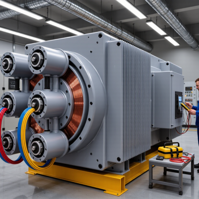
7 Tips for Choosing a Step Up Transformer

Understanding How a Step-Up Transformer Works

A step-up transformer increases AC voltage through electromagnetic induction. Alternating current in the primary winding creates changing magnetic flux in the laminated core. That changing flux induces voltage in the secondary winding. If the secondary has more turns, its voltage is higher. For example, a 100-turn primary and 500-turn secondary have an ideal ratio of 1:5. A 120-volt input would produce about 600 volts with no load. Real units differ slightly. Winding resistance, core losses, and the load cause voltage drop. The turns ratio is only part of the story. A transformer does not create extra power; as voltage rises, available current falls, with some energy lost as heat.

To understand how a transformer will work in an installation, check the input voltage, output voltage, frequency, and load rating. The unit must match the supply’s AC frequency; applying DC can quickly overheat its windings. Include the load’s starting surge, not just its normal running draw. A small motor may demand several times its rated current for a moment. Also consider insulation, cooling, and the temperature around the enclosure. These details sound mundane. They matter. Output voltage can sag under a heavy load, so a no-load reading may mislead. Nameplate figures describe rated conditions, not every real setup. Have a qualified technician verify the wiring and measurements before energizing equipment.

Matching Input and Output Voltage Requirements

7 Tips for Choosing a Step Up Transformer
Matching Input and Output Voltage Requirements

Start with the measured supply voltage and the equipment’s required voltage. For example, raising 208 volts to 480 volts requires an ideal turns ratio of about 2.31:1. Real operating voltage can vary with load, so check the transformer’s nameplate and voltage regulation, not just the ratio. Confirm phase and frequency too. A mismatch can cause poor performance or overheating.

Tip: Check input voltage at the installation point. Tip: Confirm the required output under load. Tip: Match single-phase or three-phase service. Tip: Verify frequency. Tip: Review tap settings for supply variations. Tip: Allow for expected load growth. Tip: Have a qualified engineer verify the final selection. The arithmetic is simple; site conditions are not. A 480-volt motor may draw a different current during startup than during steady operation, so include that demand when checking transformer capacity.

Voltage matching also affects efficiency and operating cost. The U.S. Department of Energy’s 2013 distribution-transformer standards analysis estimated cumulative national energy savings of 3.63 quadrillion Btu over 30 years. That figure covers efficiency standards, not voltage matching alone, but it shows why selection details matter. If the supply voltage fluctuates, record its range before choosing taps. One overlooked detail can force a costly redesign.

Calculating Load Capacity and Transformer Rating

A step-up transformer is rated in kVA, not just kW. For a single-phase load, calculate kVA as volts × amps ÷ 1,000. For three-phase, use √3 × line voltage × line current ÷ 1,000. A 4.8 kW load at 0.80 power factor needs 6 kVA. Adding a 25% planning allowance gives 7.5 kVA. That allowance is a design choice, not a universal rule. Check primary and secondary voltages, frequency, duty cycle, and available ratings before selecting a unit.

Numbers can deceive. Motors may draw several times their running current during startup. Welders, rectifiers, and variable-speed drives can also create uneven or distorted loads. Account for simultaneous operation, room temperature, ventilation, and likely expansion. Otherwise, a unit that looks adequate on paper may run hot in a dusty equipment room. IEEE Std C57.91-2011 uses a 110°C winding hot-spot as the reference point for normal insulation aging in transformers with thermally upgraded paper insulation. This is a thermal-aging benchmark, not permission to overload. Verify applicable derating data and seek engineering review for unusual starting or harmonic loads. I once treated spare capacity as a comfort number. It was not.

Choosing the Right Phase and Connection Type

Before selecting a step-up transformer, confirm the phase of both the supply and the equipment. A single-phase load generally needs a single-phase transformer; a three-phase motor usually needs a compatible three-phase unit. Check the equipment nameplate, not just the plug or cable. A mismatch can cause poor performance or prevent the load from starting. Small detail. Big consequences.

Then compare winding connections, such as delta-delta, delta-wye, or wye-wye. These arrangements affect whether a neutral is available and how the system handles grounding and certain imbalances. For example, a wye secondary may provide a neutral for suitable line-to-neutral loads, while a delta connection typically does not. The right choice depends on the site wiring and load, not on a preference for one label. I have seen selection decisions made from voltage alone; that shortcut leaves important questions unanswered.

Ask a qualified electrical professional to verify the source connection, required output, grounding method, and transformer nameplate before installation. Also check whether the load includes motors, controls, or sensitive electronics, since their starting and operating needs can differ. If the existing system is unusual, pause and document it. A clear wiring diagram helps, though it may not show every field change.

7 Tips for Choosing a Step-Up Transformer: Choosing the Right Phase and Connection Type

Phase Selection: Number of AC Phases

The chart shows the phase count of each system type: single-phase systems have one phase, while three-phase systems have three. Choose a transformer that matches the source and load requirements. Then select a connection, such as delta or wye, based on the required voltage, neutral availability, grounding scheme, and equipment specifications. Confirm the design against the transformer nameplate and applicable electrical requirements.

Checking Efficiency, Safety, and Installation Requirements

Choosing a step-up transformer starts with the load, not just the voltage difference. Check the input and output voltage, frequency, and the equipment’s rated power. Add the power needs of every connected device, then allow headroom for startup surges, especially with motors. A transformer running near its limit can heat up and lose efficiency. Look for published efficiency data at a load similar to yours; peak-efficiency figures alone may not reflect everyday use. Small loads matter, too. An oversized unit can waste energy when lightly loaded.

Safety depends on more than a sturdy case. Confirm that the transformer has suitable overcurrent protection, secure terminals, and an enclosure suited to its location. Keep ventilation openings clear, and leave space around the unit so heat can escape. Check the wiring diagram and grounding requirements before installation. That detail is easy to miss. If the supply circuit, wiring, or protective devices are unclear, have a qualified electrician assess the setup. A quick visual check is not enough.

Installation needs can change the right choice. Measure the available space, note the mounting position, and consider cable entry and access for maintenance. A unit placed in a hot, dusty cabinet may need different cooling and enclosure protection than one in a clean, open room. Record the actual input voltage under operating conditions when possible; supply voltage can vary. I would also recheck the load after installation, since real equipment does not always behave like its nameplate suggests.

7 Tips for Choosing a Step Up Transformer - Checking Efficiency, Safety, and Installation Requirements

Tip What to Check Practical Guidance
1. Match the input and output voltages Confirm the source voltage, required load voltage, frequency, and transformer connection. Choose a step-up ratio that suits the actual supply and load. For example, a nominal 120 V-to-240 V transformer has a turns ratio of approximately 1:2. Check the nameplate and wiring diagram; voltage and frequency compatibility matter.
2. Size for the load Check the load’s rated voltage, current, apparent power (VA), and starting or inrush current. For a single-phase load, apparent power is approximately volts × amps. Select a transformer with a VA rating that meets the load requirement, allowing for manufacturer guidance on motor starting, pulsed loads, and other high-inrush equipment.
3. Compare efficiency and losses Review efficiency at the expected operating load, no-load loss, and load loss. Efficiency is useful output power divided by input power. Compare published test data under similar conditions; efficiency varies with load and power factor. Low no-load loss can be especially relevant when a transformer remains energized for long periods.
4. Verify electrical protection Check overcurrent protection, short-circuit requirements, grounding, and any required disconnect. Transformer windings and connected conductors require protection appropriate to the installation. Follow the transformer instructions and applicable electrical codes; a qualified electrician should determine protective-device ratings and placement.
5. Check insulation and operating conditions Confirm insulation and temperature ratings, enclosure rating, ambient-temperature limits, and duty cycle. Choose an enclosure suitable for the location, such as protection against dust or moisture where needed. Do not assume an indoor-rated unit is suitable outdoors. Keep operation within the manufacturer’s temperature and load limits.
6. Plan ventilation and mounting Review the installation clearances, mounting orientation, weight, and heat dissipation requirements. Install the unit on a suitable support and preserve the clearances specified by its manufacturer. Keep vents unobstructed and provide adequate airflow; transformers generate heat during operation.
7. Confirm wiring and commissioning needs Check terminal markings, conductor sizes, connection diagrams, and whether the load requires a neutral or specific phase arrangement. Verify connections against the nameplate and wiring diagram before energizing. Installation should be completed by a qualified person, with supply isolated during wiring and voltage checked at the load after commissioning.

Contact Us Today for a Free Quote

(800) 708-6036