
How to Choose the Right Laser Cut Parts?
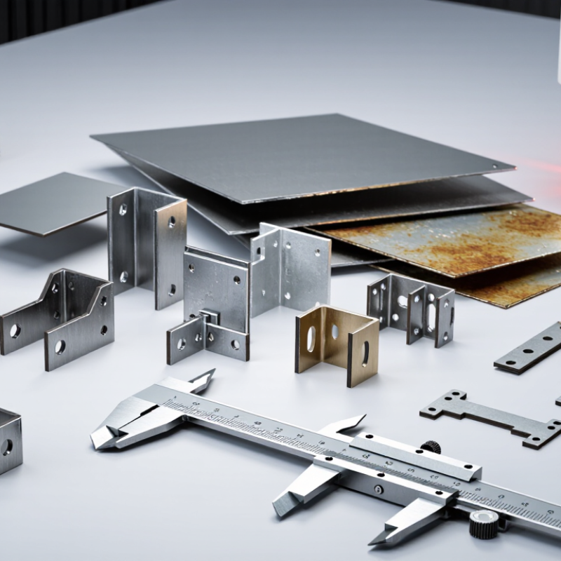
Choosing the right laser cut parts is more than selecting a material and uploading a CAD file. The decision affects fit, strength, appearance, production cost, and delivery reliability. A thin stainless steel bracket may look simple, yet its slot width, edge condition, and bend allowance can determine whether it performs correctly.
In practice, begin with the part’s working environment. Will it face moisture, heat, vibration, or repeated loading? Mild steel suits many structural applications, while aluminum reduces weight and stainless steel offers stronger corrosion resistance. Material thickness also matters. A very thin sheet may warp during handling, but an overly thick sheet can increase cutting time and leave more noticeable heat marks.
Tolerance deserves careful attention. Not every dimension needs extreme precision. Specifying ±0.1 mm across an entire drawing can raise costs without improving the assembly. Define critical features instead, such as a mounting hole aligned with a mating shaft. Check kerf width, corner geometry, burrs, and the heat-affected zone before approving production. These details are easy to overlook.
Supplier capability is equally important. Ask about laser power, maximum sheet size, inspection methods, surface finishing, and packaging protection. Request a sample when appearance or fit is uncertain. A clean edge on a showroom panel may require different finishing from an internal support bracket. The first choice is not always the best choice. Reconsider it.
This guide explains how to compare laser cut parts with practical judgment, clear specifications, and realistic expectations. The goal is not simply a cheaper part. It is a dependable part that fits, functions, and remains suitable throughout its service life.
Define the Application and Performance Requirements
How to Choose the Right Laser Cut Parts?
Define the Application and Performance Requirements
Choosing laser cut parts should begin with the job they must perform. A decorative panel needs different specifications from a load-bearing bracket. Define the expected force, movement, temperature, moisture, and service life. These details guide material selection, thickness, edge quality, and dimensional tolerance.
In practical projects, unclear requirements often cause more trouble than cutting errors. A thin steel part may reduce weight, but it can bend under repeated loads. Aluminum may resist corrosion, yet its softer surface can show marks during handling. Consider holes, slots, bends, and mounting points together. A tolerance that looks reasonable on paper may fail during assembly. I have learned that a simple prototype can reveal this quickly. Still, prototypes do not replace proper inspection.
Tips: List every operating condition before ordering. State critical dimensions separately from non-critical ones. Request material certificates when traceability matters. Check cut edges for burrs, heat discoloration, and warping. Test the part in its real assembly, not only on a workbench.
Performance requirements should also reflect the manufacturing process. Very narrow features may weaken after cutting. Closely spaced holes can distort the surrounding material. Ask an experienced engineer or qualified fabricator to review the drawing before production. This extra review may feel unnecessary, but it often prevents expensive revisions. Specification documents should include material grade, thickness, tolerance, surface expectations, quantity, and inspection method.
How to Choose the Right Laser Cut Parts? - Define the Application and Performance Requirements
| Application | Typical Material | Common Thickness | Key Performance Requirement | Recommended Cutting Considerations | Typical Tolerance Guidance | Recommended Post-Processing |
|---|---|---|---|---|---|---|
| Electrical Enclosures | Mild steel or stainless steel | 1.0–3.0 mm | Dimensional stability, clean edges, corrosion resistance, and reliable panel fit | Use pierce points away from visible surfaces; specify hole-to-edge distances and bend clearances | About ±0.10–0.25 mm for many sheet-metal features, depending on size and process | Deburring, bending, powder coating, wet painting, or passivation for stainless steel |
| Machine Guards and Safety Covers | Mild steel, stainless steel, or aluminum | 1.5–6.0 mm | Impact resistance, adequate stiffness, safe edges, and secure mounting | Add vent slots or inspection openings without creating sharp internal corners; maintain structural webs | General profile tolerance commonly specified around ±0.20–0.50 mm | Edge rounding or deburring, bending, and protective coating where required |
| Automotive Brackets and Mounting Plates | Carbon steel, stainless steel, or aluminum | 2.0–8.0 mm | Load-bearing capacity, hole-position accuracy, vibration resistance, and repeatability | Control heat distortion; define datum features, critical hole sizes, and flatness requirements | Critical hole and position tolerances should be specified separately; general features often use ±0.10–0.30 mm | Deburring, bending, welding, zinc coating, e-coating, or powder coating |
| Architectural Panels and Decorative Components | Aluminum, stainless steel, or weathering steel | 1.0–4.0 mm | Visual consistency, surface quality, corrosion resistance, and accurate pattern alignment | Place lead-ins outside visible areas; maintain consistent kerf compensation for repeated patterns | Typically ±0.20–0.50 mm for profile dimensions, subject to panel size and material | Brushing, anodizing, powder coating, polishing, or clear protective coating |
| Food-Processing Equipment | Food-contact stainless steel | 1.0–3.0 mm | Hygienic surfaces, corrosion resistance, cleanability, and minimal particle retention | Avoid narrow inaccessible gaps; specify edge condition and surface-finish requirements before cutting | Use application-specific tolerances; non-critical profiles commonly fall near ±0.20–0.30 mm | Thorough deburring, passivation, electropolishing, and removal of heat tint where necessary |
| HVAC Duct and Ventilation Parts | Galvanized steel, mild steel, or aluminum | 0.8–2.0 mm | Airflow efficiency, leak prevention, dimensional fit, and low assembly time | Use correctly sized tabs, slots, and bend reliefs; protect coated surfaces during handling | Often ±0.20–0.50 mm for cut features, with bend accuracy defined separately | Deburring, bending, seam sealing, and touch-up of damaged protective coatings |
| Laboratory and Medical Equipment Frames | Stainless steel or aluminum | 1.0–4.0 mm | Cleanability, dimensional repeatability, low distortion, and resistance to cleaning chemicals | Define critical mounting datums and avoid burrs around access holes and interfaces | Commonly ±0.10–0.30 mm for important mounting features, subject to design review | Deburring, passivation, brushing, electropolishing, or powder coating |
| Prototype and Low-Volume Product Parts | Mild steel, stainless steel, aluminum, or brass | 0.5–6.0 mm | Fast iteration, predictable fit, material availability, and controlled cost | Use standard materials and avoid unnecessarily tight tolerances that increase manufacturing cost | Use general tolerances for non-critical features and tighter tolerances only where function requires | Deburring, bending, tapping, countersinking, and temporary or final surface finishing |
Note: Tolerance ranges are typical planning values for laser-cut sheet-metal parts. Final capability depends on material grade, thickness, part size, geometry, machine condition, heat input, and inspection method.
Related Posts
-

How to Choose the Best Pipe Laser Cutting Machine?
-
Why Pipe Laser Cutting is the Future of Precision Manufacturing?
-
What Is CNC Cutting and How Does It Work?
-
Top 10 CNC Laser Cutting Machines for Precision Fabrication in 2023
-
How to Choose the Best CNC Laser Table for Your Projects?
-
Top Fiber Laser Cutter Manufacturers for Global Buyers